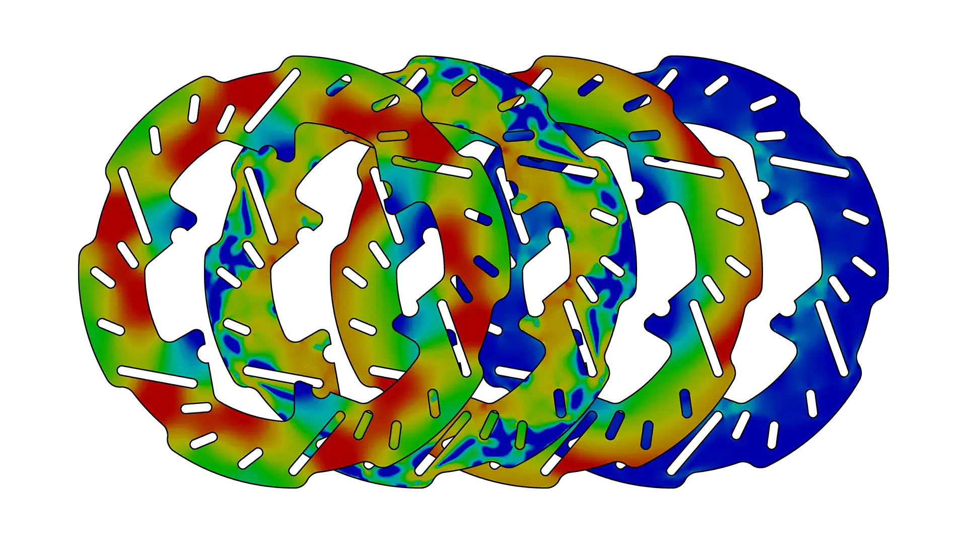
Brake Rotor Thermal-Structural Analysis, Validated Against Telemetry
ClientEESC-USP Formula SAE
- FEA
- CFD
- Thermal Analysis
Result
Coupled FEA/CFD model correlated directly against track telemetry
The problem
A race brake rotor’s performance depends on geometry decisions that all trade off against each other — mass-relief placement affects cooling, structural integrity, and rotational inertia simultaneously. Getting that balance wrong either costs performance or risks the rotor’s structural integrity under real thermal and mechanical load, and neither simulation alone tells the full story.
Approach
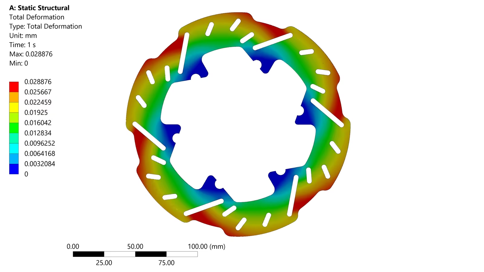
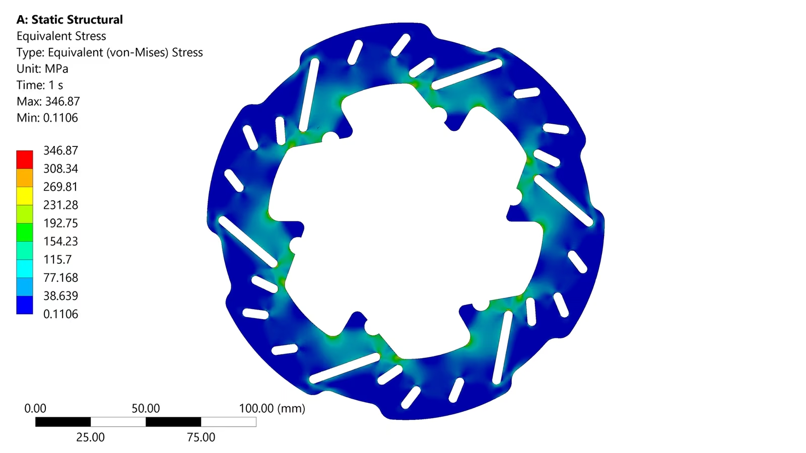
Thermal FEA modeled the rotor and adjacent components under real duty cycles: thermal expansion and contraction, ventilation-slot placement, warping, creep, high-temperature fatigue, and metallurgical effects like phase transformation. The same FEA model captured the mechanical side — stress and fatigue behavior that flags cracking, yielding, or failure risk before a physical part exists. Separately, CFD modeled the brake system’s surroundings — airflow and cooling around the rotor and caliper — to catch cooling performance issues and validate the aerodynamic features placed to address them, predicting temperature distribution and heat dissipation across the critical areas.
The step that made the models trustworthy rather than theoretical was correlating both against real track telemetry from competition, rather than validating only against idealized bench conditions.
Result
The correlated model gives a rotor design process grounded in how the car is actually driven and braked, not just how a dynamometer represents it — catching design issues before a physical prototype, and cutting the cost of iterating toward a rotor that performs under real thermal and mechanical load without over-building it.
Why it matters for your program
Thermal-structural components are exactly where simulation pays for itself fastest — a failure mode caught in FEA costs an afternoon; the same failure mode caught after manufacturing costs a part, a test day, and possibly a car.
Compare
Drag to compare the two cases
Have a similar problem?
Coupled FEA/CFD model correlated directly against track telemetry. Tell me what you're working on and I'll tell you directly whether and how I can help.
I reply to every enquiry within one business day.
+55 16 99785-1402