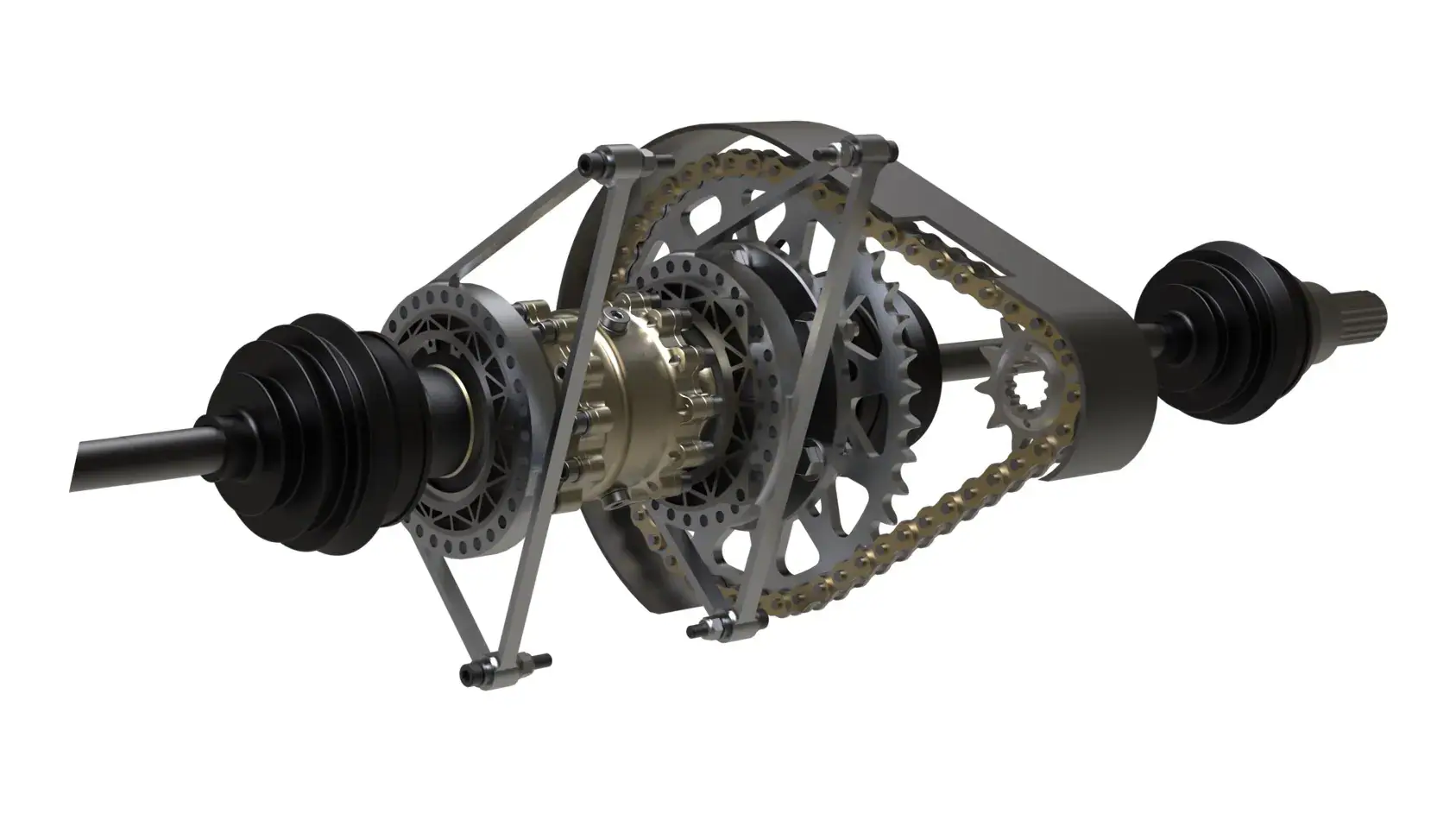
Topology-Optimized Differential Sprocket
ClientEESC-USP Formula SAE
- FEA
- Topology Optimization
- Mechanical Design
The problem
Prior differential sprocket designs were showing excessive wear and radial runout — a failure risk serious enough to threaten the chassis, engine, and differential downstream of it. The part needed a full redesign: lighter, but rated to a 1.4 minimum safety factor across a calculated 1500km of testing and competition life.
Approach
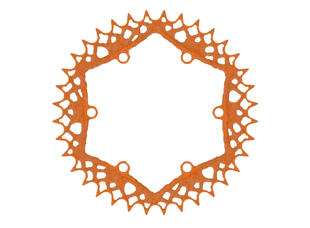
The fatigue cycle driving the optimization is a superposition of two things: the chain-engagement cycle (which varies with wheel rotation frequency, and where tooth-to-tooth load increases exponentially from first to last engaged tooth due to hysteresis and chain wear) and the car’s acceleration/deceleration cycle over a lap. Engine braking — which can reach 50% of engine power once pumping, thermal, viscous, and valvetrain losses are accounted for — had to be modeled too, since it’s weaker than drive torque and is exactly why the optimized geometry ends up asymmetric.
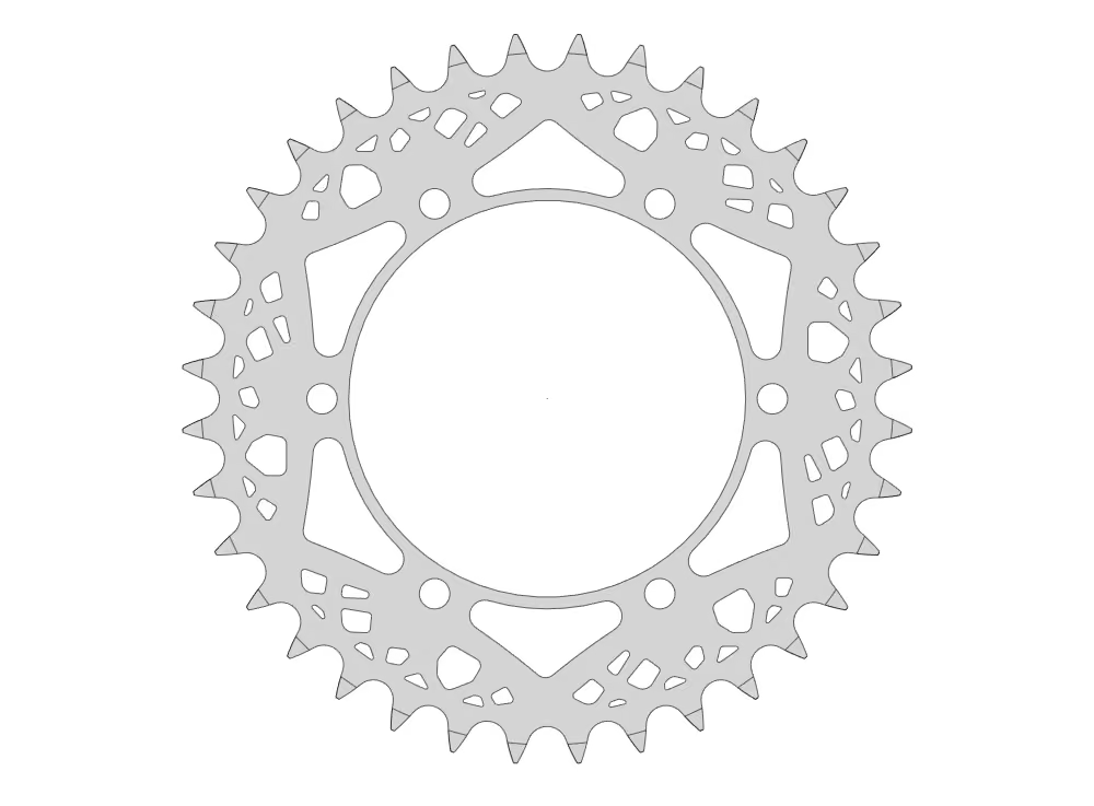
Topology optimization on a thin structure like this pays off doubly: the resulting geometry is both lighter and simple to manufacture. The final part, cut from AISI 7075-T6 aerospace aluminum via waterjet (chosen for precision without disturbing the material’s thermal treatment), got a 60µm hard-anodized layer for a 560HV surface microhardness — enough to resist crack growth from chain engagement while cutting friction and wear at the contact surface.
Result
The optimized geometry came out 22% lighter than the previous design while meeting the fatigue and safety-factor targets, and was subsequently validated by harmonic response testing against the simulation’s mechanical and material assumptions.
Why it matters for your program
Topology optimization earns its keep fastest on thin, highly-loaded structural parts like this one — where the “obvious” shape almost never survives contact with a real fatigue-cycle model, and where the optimized result is often cheaper to manufacture, not more expensive.
Walkthrough
How it came together
- 01
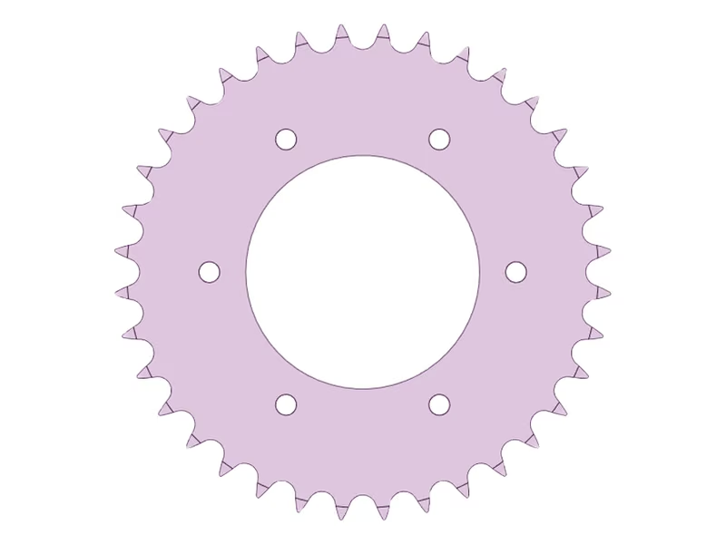
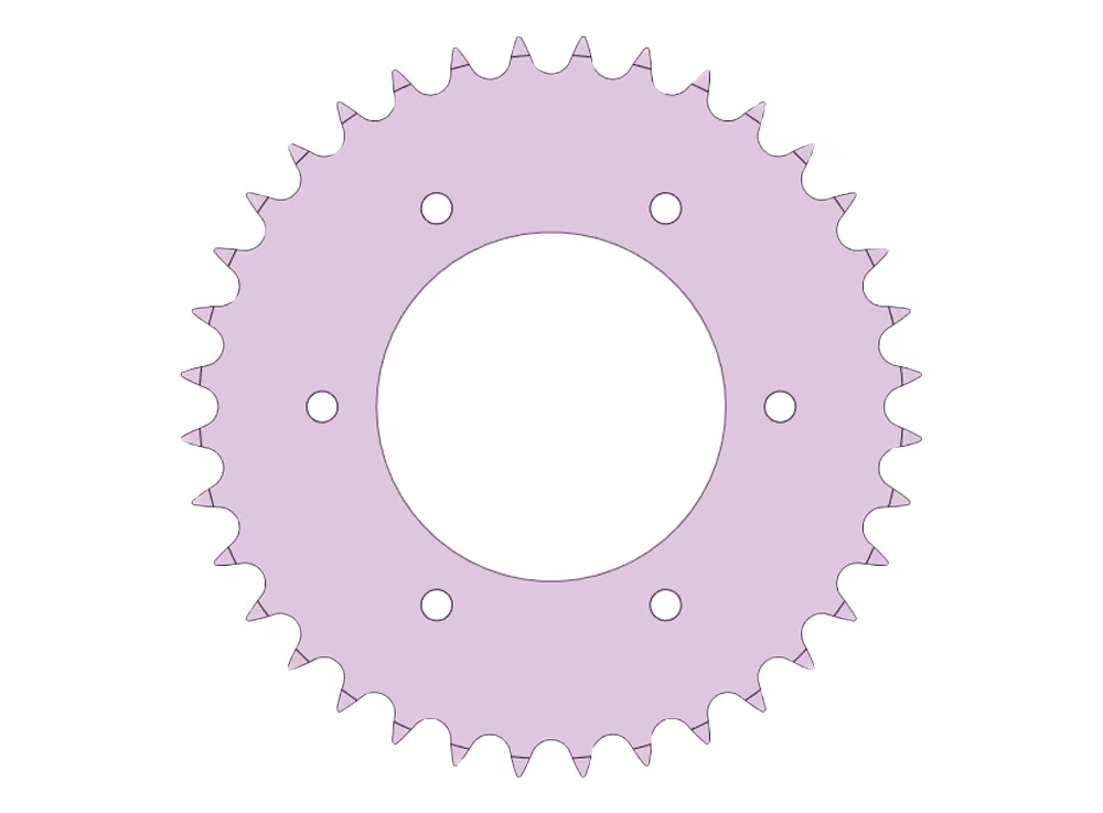
Initial rear sprocket geometry prior to topology optimization
- 02
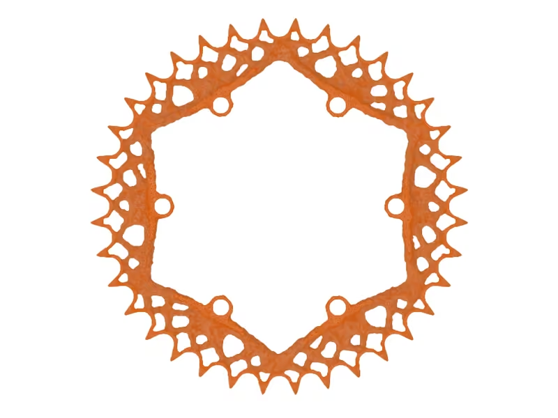
Topology optimization result under combined forward-power and braking loads
- 03
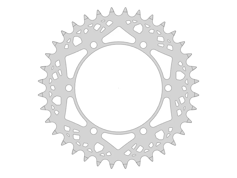
Production-ready sprocket with stabilization supports and contact improvements
Have a similar problem?
−22% mass, 1.4 min safety factor across a 1500km fatigue life. Tell me what you're working on and I'll tell you directly whether and how I can help.
I reply to every enquiry within one business day.
+55 16 99785-1402